An introduction to running a control system with PCTMonitor.
- Start the PCTMonitor application
If you get this warning just click “Disable Modules and Continue”.

- The GUI appears.

- We are going to test a simple control system configuration represented by this diagram,
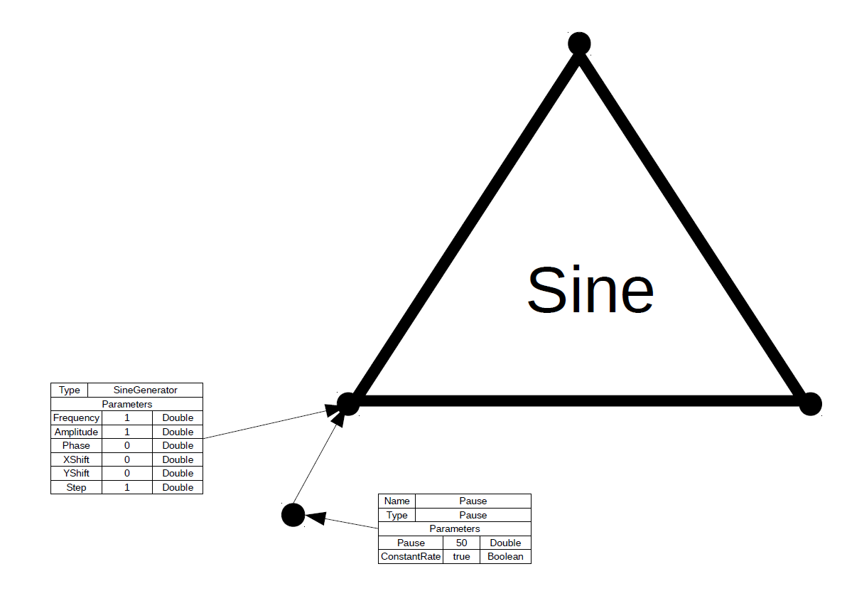
The triangle represents a PCT control system and the circles are functions. Functions are in use if they are configured with a properties box. So, in this case there are only two functions, a sine generator and a pause function, which regulates the iteration rate.
- The file for this configuration is found in the release folder as 000-000-SineTest.odg. Download it to a workspace folder.
- In the GUI click the “Open File” button and navigate to this file.
- You should now see two tabs “ControlPanel Window” and “PlotPanel Window“. You can drag the latter out of the main window so that you have two separate windows.
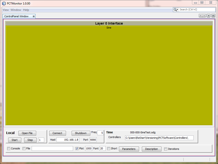
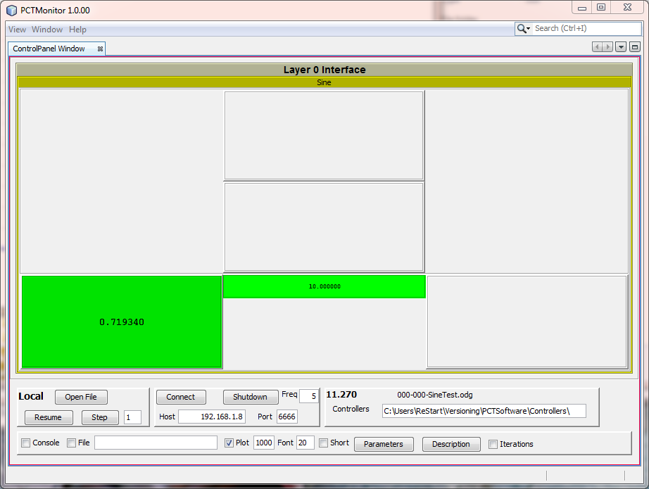
- “ControlPanel Window” will look like this,
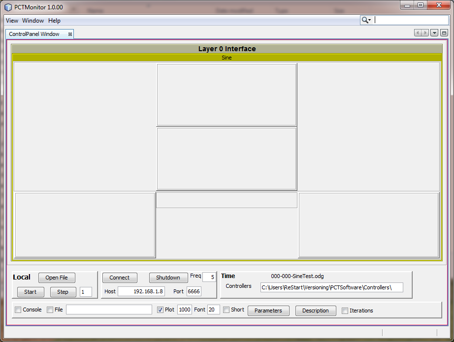
- Click on the word “Sine” and the display will open up to,
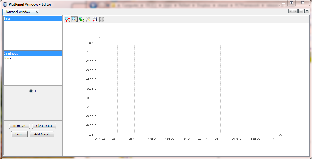
- In the “PlotPanel Window” click on the word “Sine” and then “SineInput“,
- In “ControlPanel Window” click the “Start” button and you will see the control system run with values being displayed in “ControlPanel Window” and plotted in “PlotPanel Window,“

- Click on the “Parameters” button to get the parameters window,
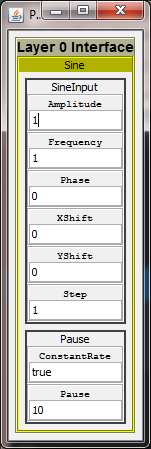
- Changing these parameters will have an immediate effect on the live control system values.